sensor-enclosure-thermal-design
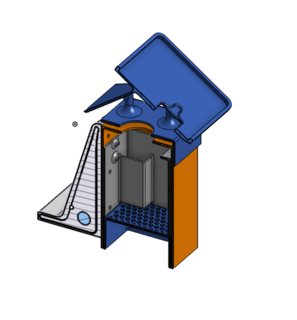
Field-deployed sensor enclosure for air-quality hardware, designed around airflow, rain-path control, internal electronics packaging, clamp mounting, and ESP32 power reliability.
Result. Restored the ESP32 rail from a 2.1 V brownout to 4.1-4.3 V and screened a 140 mph wind case across four enclosure revisions.
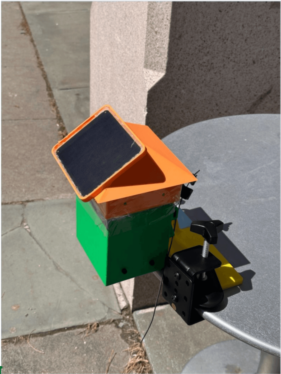
The enclosure packages gas and particulate sensors, ESP32, GPS, solar and LiPo power on a clamp mount that survives weather without blocking sensor airflow. The current unit is deployed outdoors; thermal and calibration qualification are pending in the linked repository.
| Category | Mechanical Prototyping / Environmental Sensing |
|---|---|
| Timeline | Dec. 2025 - Present |
| Status | Outdoor Prototype Deployed |
| Evidence | Outdoor prototype; qualification pending |
| Role | Mechanical enclosure design, sensor packaging, CAD iteration, FDM prototype fabrication, structural screening, clamp integration, and power-debug support |
| Tools | SolidWorks, Onshape, FDM Printing, Multimeter, Oscilloscope |
| Materials | PLA, M2 hardware, M4 hardware, solar panel, LiPo battery, ESP32, gas/particulate sensors |
| Links | RepositoryThermal model results |
problem
My contribution. Enclosure CAD, roof and vent geometry, internal sensor housing, clamp integration, FDM fabrication, wind-load screening, and ESP32 power debugging.
A compact outdoor node has to admit air to the sensors while shedding rain, hold a battery, solar wiring, and a custom PCB, and stay serviceable. The clamp mount also has to carry wind load without flexing the printed walls or overloading fasteners.
constraints
- Package gas and particulate sensors, ESP32, GPS, LiPo battery, solar wiring, and a custom PCB in one serviceable enclosure.
- Preserve airflow to the sensing region while blocking direct rain entry.
- Print in PLA at about 0.100 in wall with bolted M2 and M4 hardware, no heat-set inserts.
- Screen the clamp and support geometry against a 140 mph wind case.
design evolution
Iterations, issues, and fixes, recorded in the order they happened.
| Revision | Failure mode | Design change | Result |
|---|---|---|---|
| V1 to V2 | A box-like shell had no cable plan, weak clamp stiffness, and poor routing. | Added a roof concept, an external clamp feature, and an internal packaging direction. | Identified the mount-load transfer and packaging problems. |
| V3 to V4 | The outdoor prototype worked, but sensor retention, wiring, and wall flex needed work. | Gabled roof, solar panel placement, internal housing, lower mesh region, and clamp support. | Deployed outdoors with an improved load path and serviceability. |
| Power debug | The ESP32 rail oscillated from 4.5 V down to 2.1 V under the full sensor stack. | Revised switching and power routing. | Stable operation at roughly 4.1 to 4.3 V. |
results
Wind screening used two levels: a conservative wall-strip hand calculation (0.825 ksi, FoS about 5.5 against a 4.5 ksi PLA allowable) and a preliminary 3D model that spreads load through the clamp and housing (about 127 psi).
Bench integration found the ESP32 brownout under the full sensor and radio stack; revised power routing restored 4.1 to 4.3 V before deployment.
Scope note. The hand calculation and preliminary 3D model are screening methods with different assumptions, not final qualification results.
lessons
- The problem was never just a box: airflow, rain path, packaging, cable access, power reliability, printability, and clamp load transfer all traded against each other.
- The strongest change was structural: a real roof, an internal housing, a lower vent region, and clamp and back support reduced wall flex and improved serviceability.
- Remaining risks are screw-hole stress, clamp-root fillets, layer anisotropy, the cable-entry rain path, and long-term PLA exposure; water-exposure tests and a documented simulation model come next.
gallery