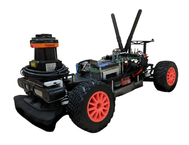
autonomous-racing-systems
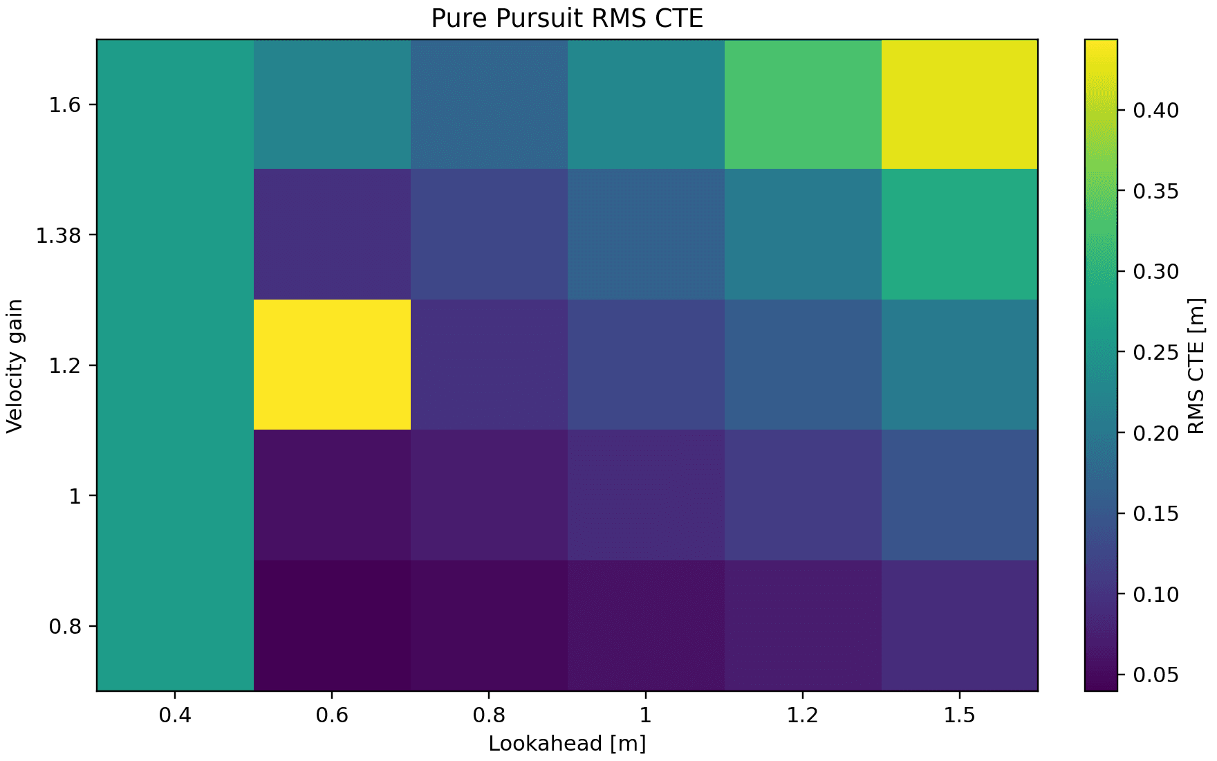
Vehicle-model identification, controller comparison, and a LiDAR mast that moved from modal failure to a converged redesign.
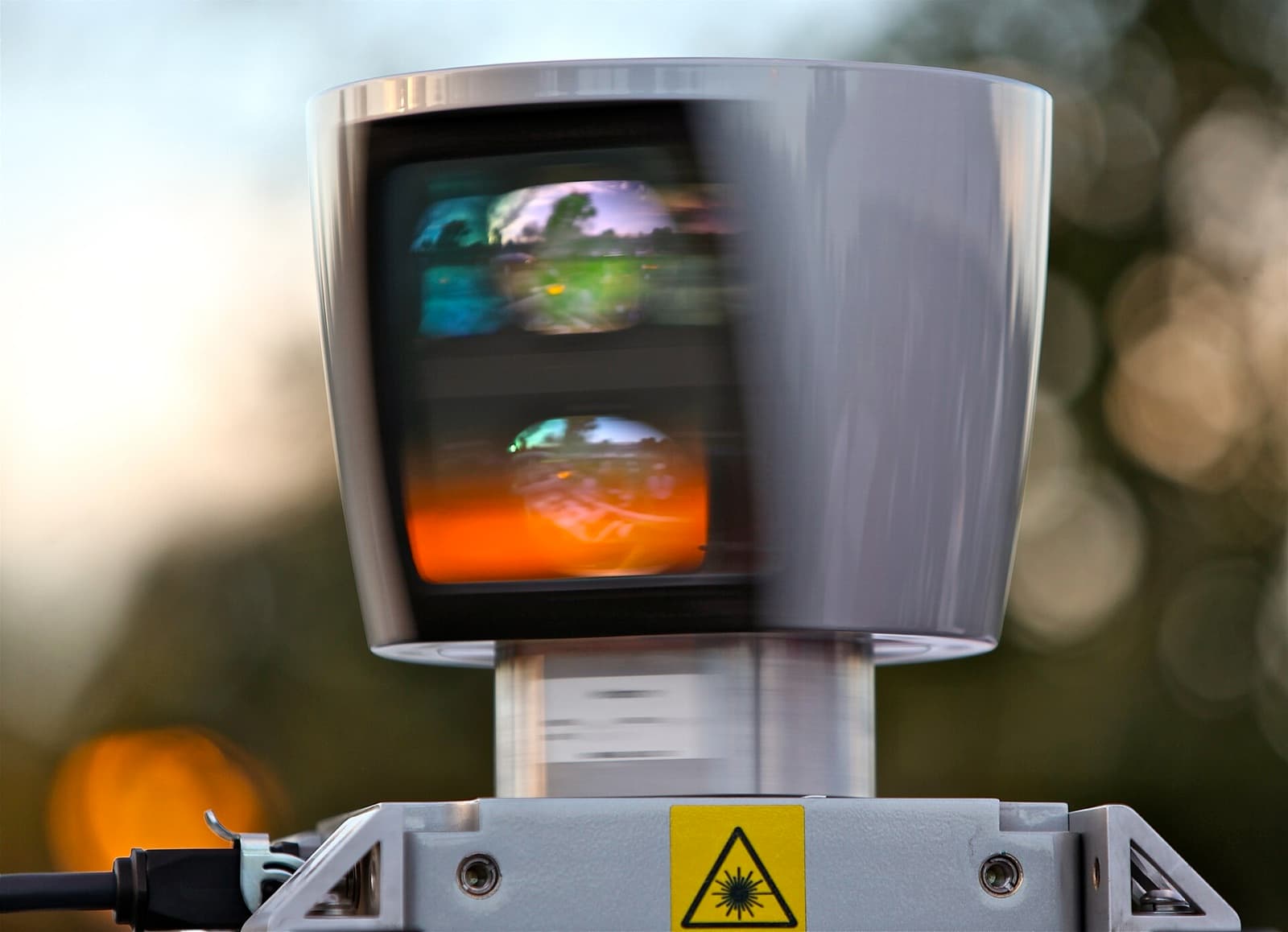
Result. Raised the mast's first mode from a failing 174.7 Hz to 285.5 Hz against a 200 Hz guard by redesigning the tube and converging three FEA meshes.
The project combines simulator-backed vehicle identification and controls with a mechanical design-review package for the LiDAR mast. The physical compliance protocol is frozen and executable; fabrication and measurement are still pending.
| Category | Robotics |
|---|---|
| Timeline | 2025 - Present |
| Status | In Progress |
| Evidence | Converged FEA; physical test pending |
| Role | Modeling, system identification, controller evaluation, mechanical analysis, FEA convergence, and physical-test design |
| Tools | Python, ROS 2, CalculiX, Gmsh |
| Materials | 6061-T6 aluminum tube, printed/machined mast fixture |
| Links | RepositoryPhysical Protocol |
problem
My contribution. Built the experiment-to-report pipeline, controller comparisons, mast hand calculations, static/modal FEA, convergence checks, tolerance stack, and preregistered compliance analyzer.
A fast RoboRacer needs defensible vehicle models and a LiDAR structure that does not corrupt the scan plane. The design had to catch failures before fabrication and connect every result to a reproducible run.
constraints
- First mast mode must exceed the registered 200 Hz guard.
- Use the locked 100 mm length, 20 mm OD, and 1.5 mm wall in CAD and fabrication.
- Physical compliance needs a 0.001 mm indicator at the planned 20 N load.
- Deflection validates compliance, not stress without strain instrumentation.
design evolution
Iterations, issues, and fixes, recorded in the order they happened.
| Revision | Failure mode | Design change | Result |
|---|---|---|---|
| Baseline analysis | The 120 mm × 16 mm mast reached only 174.7 Hz. | Shortened the mast and increased the tube diameter. | The redesigned hand model reached 330.1 Hz. |
| FEA convergence | A single mesh could make agreement look better than it is. | Ran three refinements and used gauge-region/global metrics instead of singular peak stress. | Final changes stayed below 1.5%; FEA f1 = 285.5 Hz. |
| Physical gate | A standard 0.01 mm indicator provides only about three counts at 20 N. | Registered a 0.001 mm instrument, fixture subtraction, two axes, five loads, and three cycles. | Executable verdict is ready; measurement remains pending. |
results
Simulation and FEA evidence is committed and reproducible. The physical test uses five load levels, both axes, at least three load/unload cycles, and fixture-motion subtraction.
VALIDATED requires R² ≥0.99, hysteresis ≤5%, relative U95 ≤10%, and measured as-built compliance within ±15% of as-built FEA.
Scope note. The mast has not yet been fabricated or physically tested. Current structural results are hand calculation and FEA, not measured validation.
lessons
- A failed acceptance criterion is valuable when it causes a cheaper pre-build redesign.
- Convergence and region selection matter more than a visually dramatic peak-stress contour.
- Instrument resolution should be screened against the actual planned load, not the original high-load model point.
gallery