RoboMaster Launcher Packaging and Flywheel Prototype
Prototype launcher hardware for a RoboMaster gimbal, focused on feed-path clearance, motor-interface retention, and compact subsystem packaging.
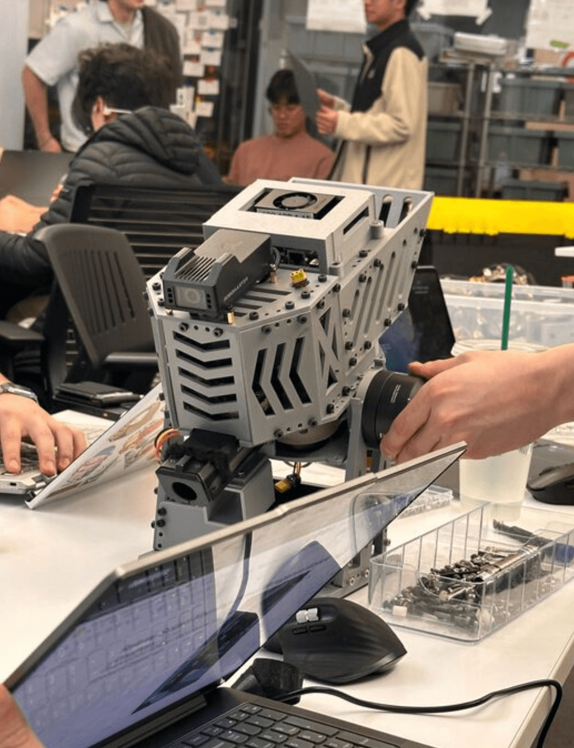
Result. Maintained 20.5 mm feed-path clearance in a 500 RPM prototype test by packaging a 78.0 mm PLA wheel and replacing press-fit-only retention with an M3 fastener.
The launcher subsystem had to fit inside an existing gimbal envelope while keeping projectile clearance and a sound motor interface. The prototype ran at the DJI M2006's 500 RPM condition; higher-speed qualification has not been done.
| Category | Robotics Hardware |
|---|---|
| Timeline | Feb. 2026 - Present |
| Status | Tested Prototype |
| Evidence | 500 RPM prototype test |
| Role | Mechanical design, CAD packaging, prototype fabrication, clearance review, retention revision, and test support |
| Tools | Onshape, SolidWorks, FDM Printing, Onshape Simulation |
| Materials | PLA, M3 hardware, DJI M2006 motor |
problem
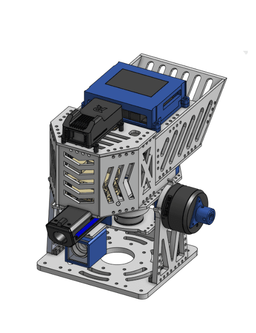
My contribution. Launcher-wheel CAD, supercapacitor enclosure shell, front armor packaging, feed-path clearance review, M3 retention revision, and 500 RPM test support.
Packaging, not part strength, was the risk: the printed wheel, supercapacitor shell, and front armor had to clear the projectile path and each other inside the gimbal, and a press-fit motor interface alone was a weak retention assumption for a rotating part.
constraints
- Fit inside the existing RoboMaster gimbal envelope and the DJI M2006 motor interface.
- Maintain about 20.5 mm projectile feed-path clearance.
- Print launcher components in PLA with symmetric wheel geometry for spin testing.
- Claim only the 500 RPM prototype condition, not high-speed launcher qualification.
design evolution
Iterations, issues, and fixes, recorded in the order they happened.
| Revision | Failure mode | Design change | Result |
|---|---|---|---|
| Packaging and feed path | Launcher hardware risked interference inside the gimbal and along the projectile path. | Modeled the wheel, armor, and supercapacitor shell around the existing geometry while holding 20.5 mm clearance. | Package envelope set with feed interference removed. |
| Motor interface | Press fit alone was a weak retention assumption. | Revised the 0.122 in / 3.10 mm interface and added M3 screw retention from the flywheel base. | Retained wheel with higher assembly confidence. |
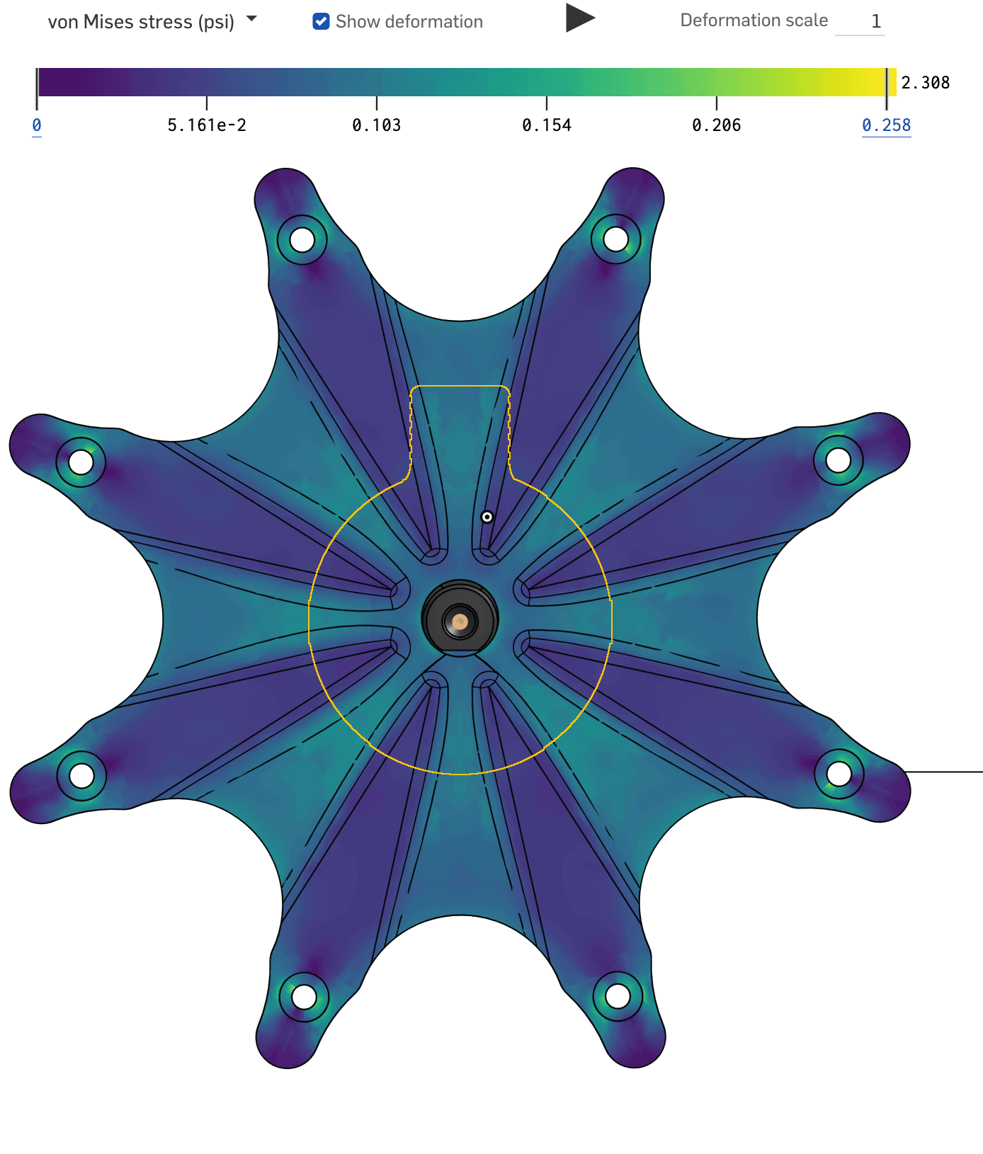
| Prototype test | The assembly needed a functional check before any higher-speed use. | Ran the wheel on the DJI M2006 at 500 RPM with Onshape screening as preliminary analysis. | Prototype-level operation confirmed; clearance held. |
results
The prototype ran at the DJI M2006 motor's 500 RPM condition with about 20.5 mm feed-path clearance maintained and the revised M3-retained motor interface installed.
Onshape simulation served as preliminary screening for the 500 RPM condition only; runout, balance, and guarded spin tests at higher speeds remain open.
Scope note. This was a 500 RPM prototype test, not high-speed launcher qualification.
lessons
- Press fit alone was not a strong enough retention assumption for a rotating prototype.
- The most important design constraint was packaging: feed-path clearance, wheel symmetry, motor interface, and surrounding gimbal geometry had to work together.
- Future work should include measured runout, documented balance checks, guarded spin testing, and stress screening before using the design with higher-speed motors.
gallery