CUSP air-quality nodes: prototype to Queens College
Four printed revisions, power-fault diagnosis, thermal modeling and a new deployment-specific assembly.
Built enclosures, measured power debugging and model-based screening
Designed four printed enclosure revisions, diagnosed the startup brownout and assembled the October 2026 Queens College node. Printed-housing material cost fell from $70 to $24, approximately 66%.
results and contributions
| Built hardware | Four printed revisions; V3 deployed outdoors; Queens College unit assembled |
|---|---|
| Printed-housing material cost | $70 inherited nylon-shell prototype → $24 PLA (approximately 66% lower) |
| Measured power debugging | 2.1 V supply sag → approximately 4.1–4.3 V operation |
| Received field records, April 20–May 11 | 4,736 received records; zero BROWNOUT flags (independently recounted November 1) |
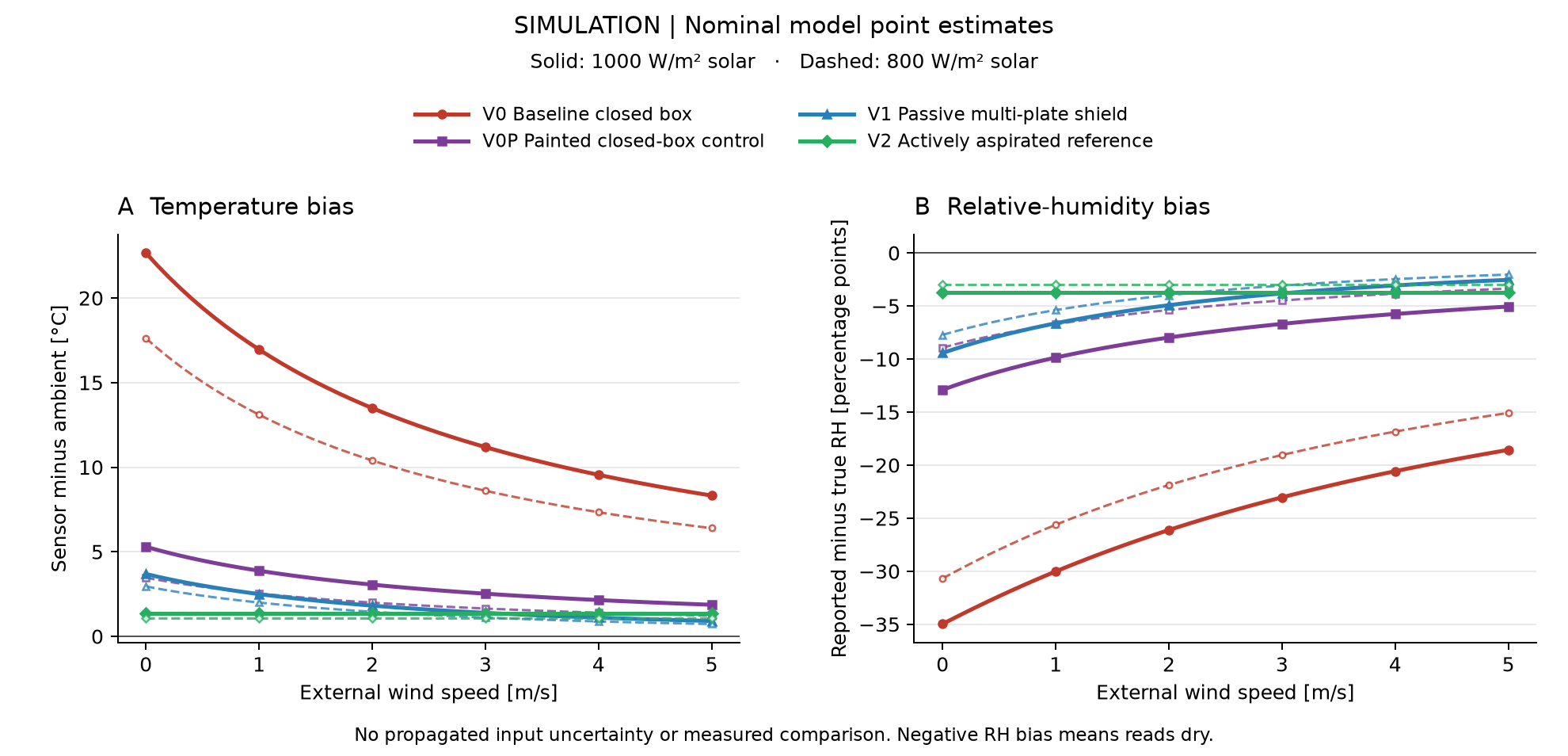
| Model conditions | 1000 W/m² solar loading; 0.5 m/s wind |
| Dark box, modeled | 19.4 °C above ambient |
| White box, modeled | 4.5 °C above ambient |
| Passive shield, modeled | 3.0 °C above ambient |
| Synthetic experiment-design study | 72 scenario cells / 2,880 fits |
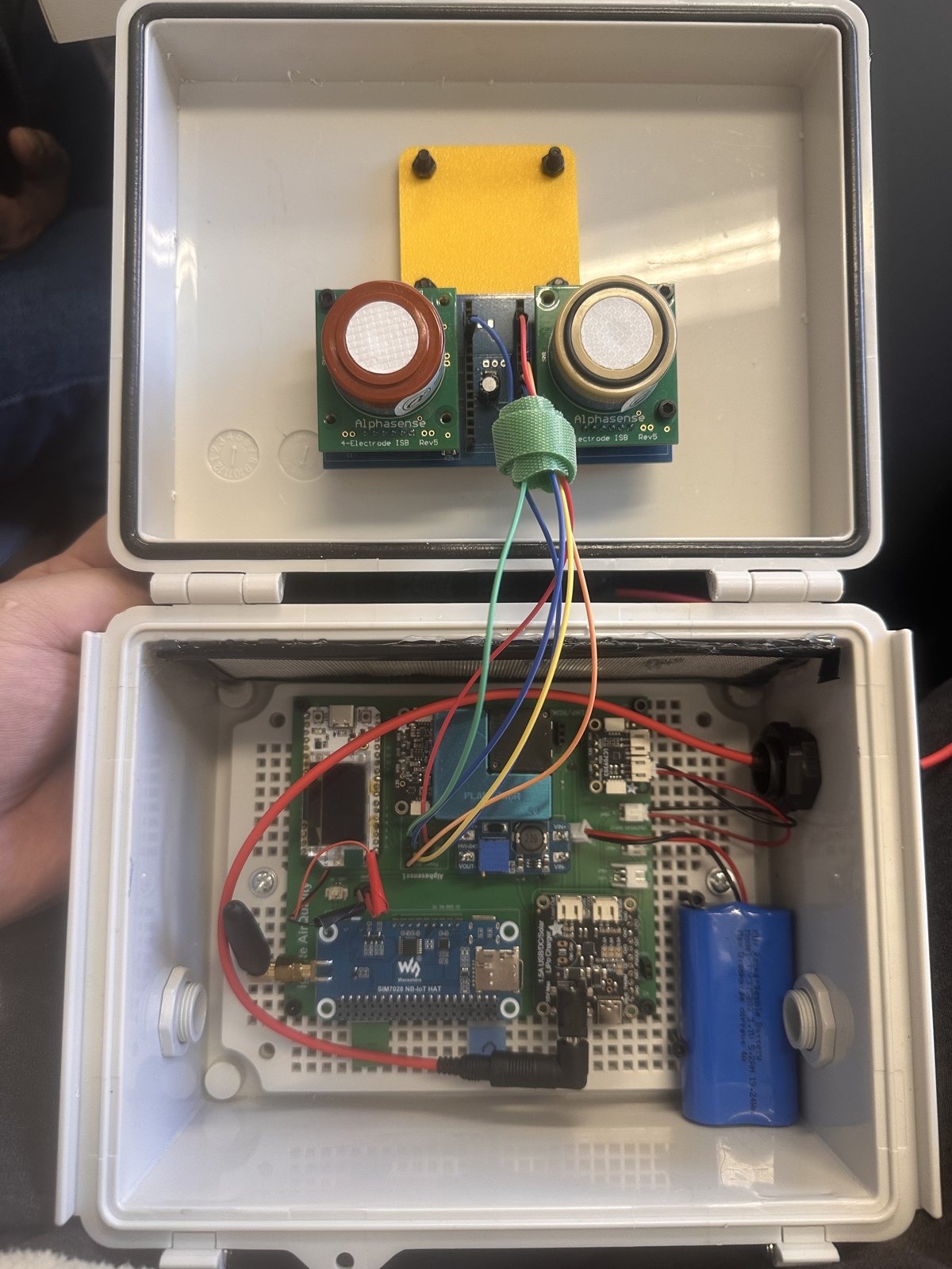
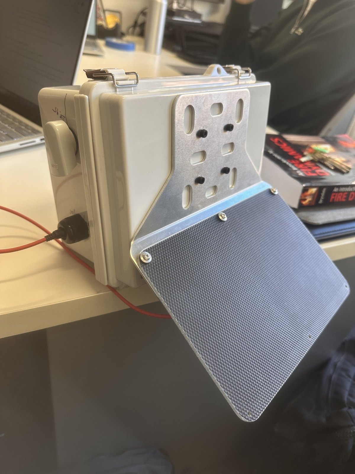
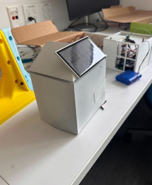
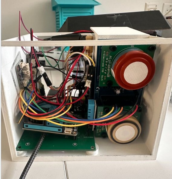
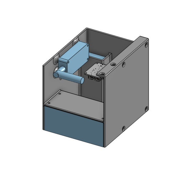
The newest physical contribution is the Queens College assembly shown below. Its purchased housing, lid-mounted sensors and offset panel create different airflow, wiring and mount conditions from the printed prototypes.
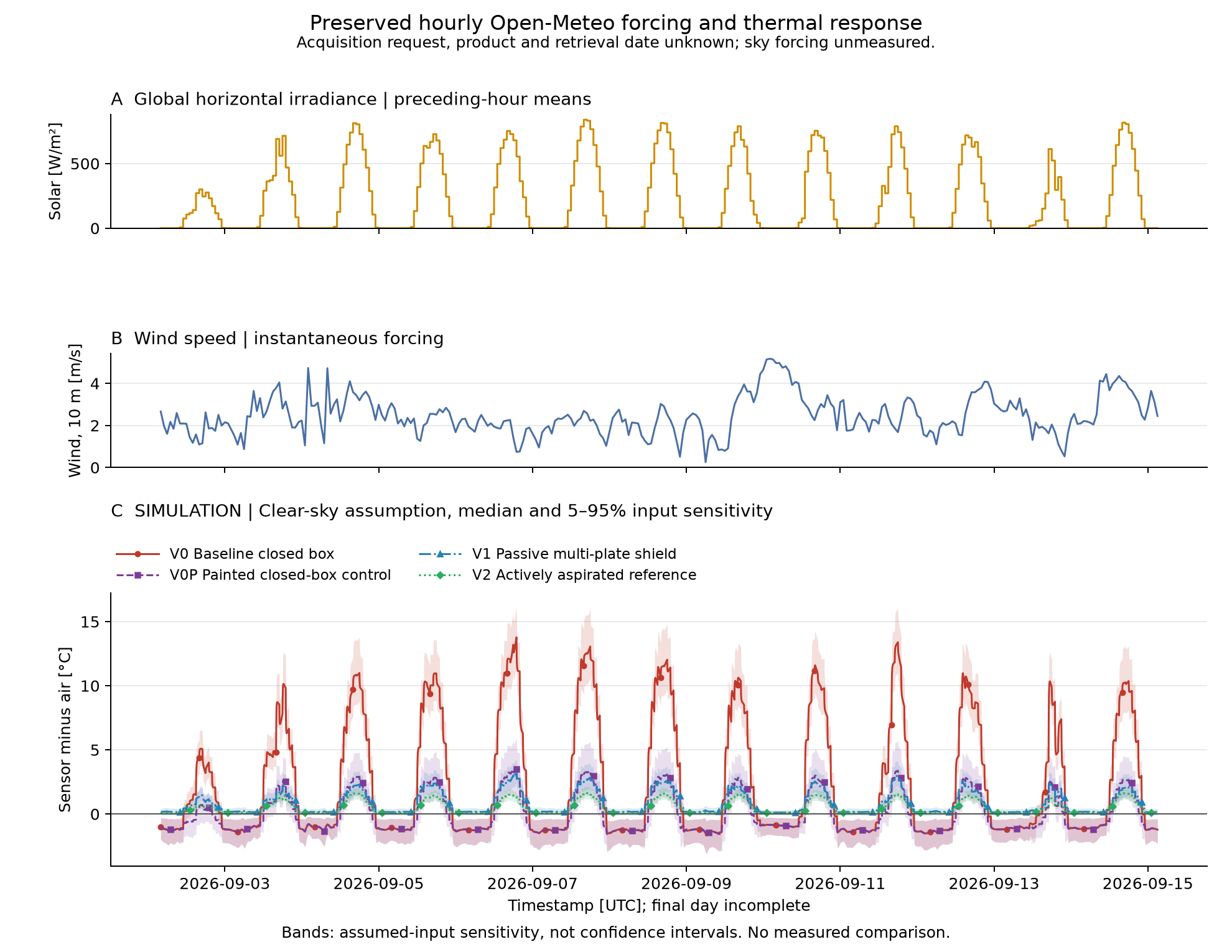
The thermal values are predictions at the stated conditions, not a measured reduction in sensor bias. The earlier synthetic experiment-design study remains a separate research result.
figures and hardware
Open any image at full size. Source links identify the retained revision.
design evolution
The design and analysis steps that produced the current work.
| Work | Engineering question | Approach | Outcome |
|---|---|---|---|
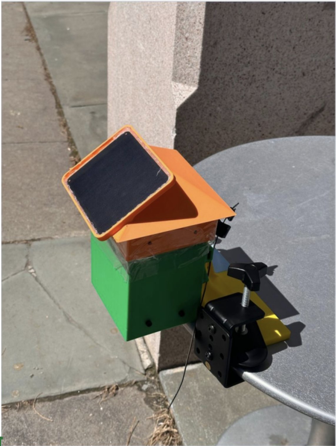
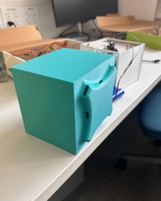
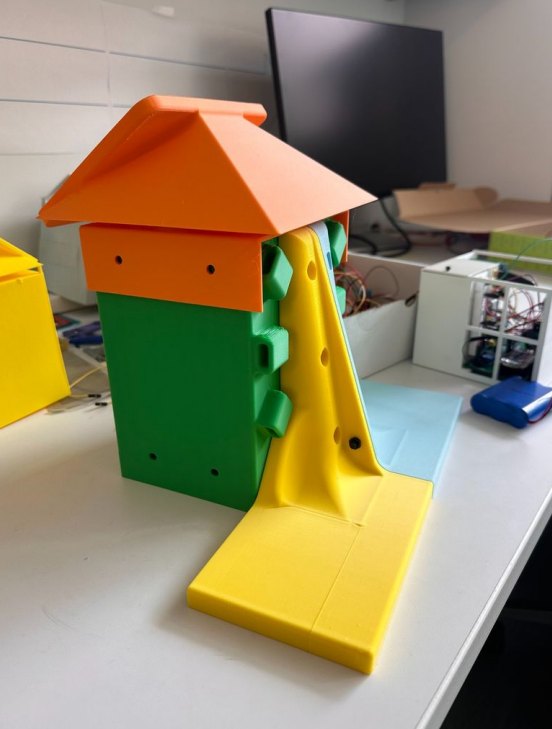
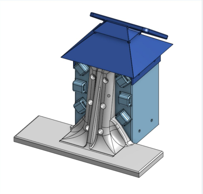
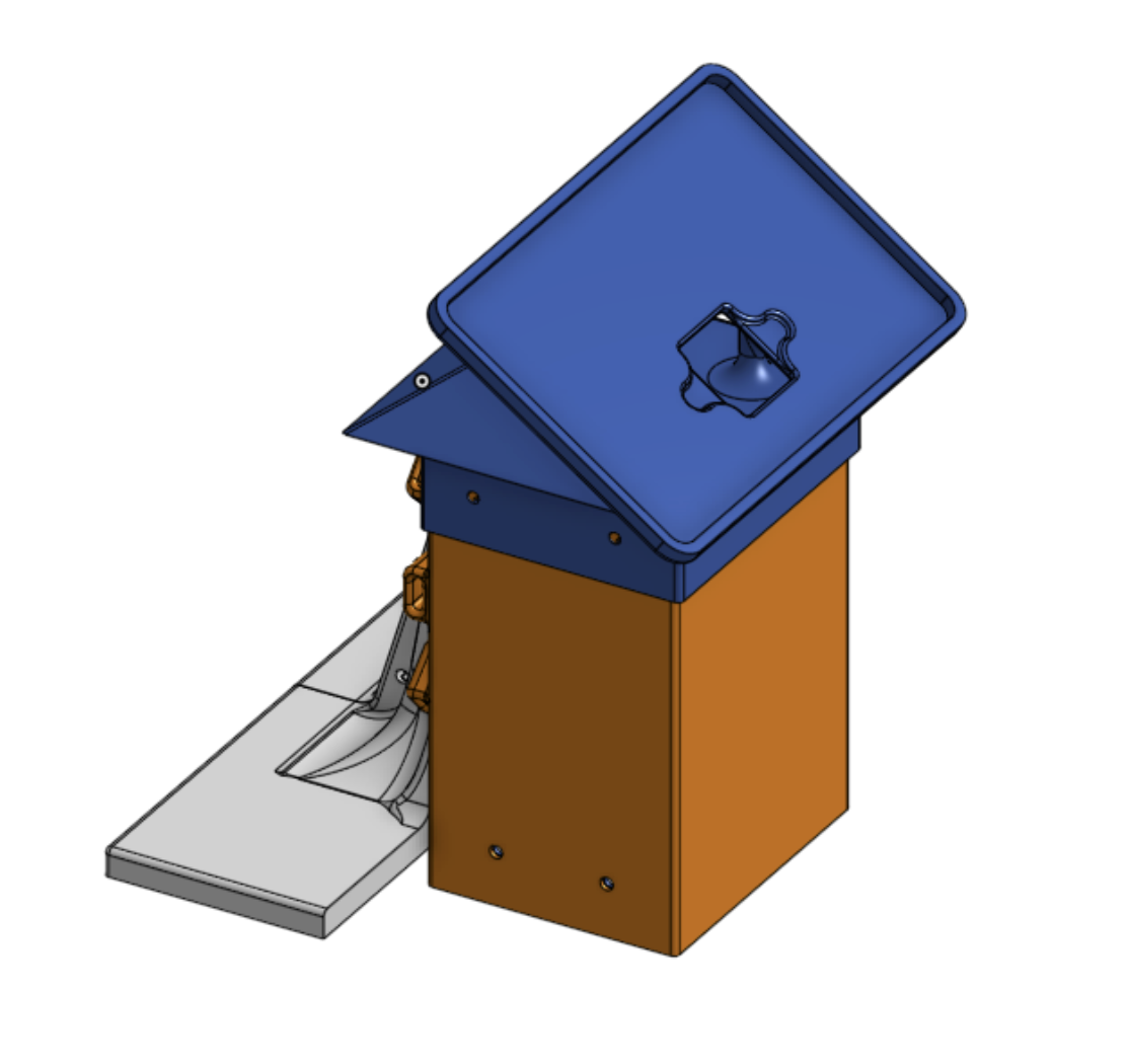
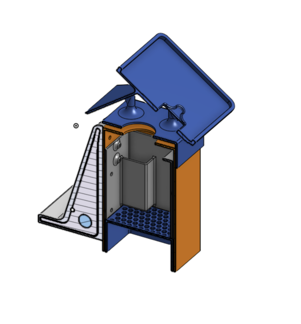
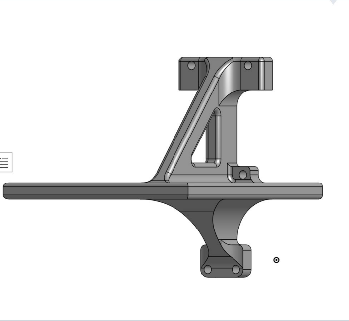
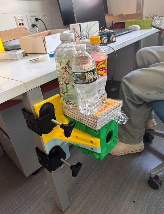
| Enclosure revisions | Airflow, rain protection, power routing and service access competed. | Iterated rain paths, roof, internal mounts, cable routes and service access through four printed versions. | V3 was deployed outdoors. V4 was built, then paused while the team focused on Queens College. |
| Printed material cost | Keep rapid enclosure iteration affordable. | Compared the inherited nylon-shell prototype with an all-PLA printed housing. | Housing material cost fell from $70 to $24, approximately 66%. The purchased deployment box has a separate BOM. |
| Startup brownout | The node repeatedly reset when the sensor and modem loads started. | Used a meter and oscilloscope to trace supply sag; revised load sequencing and power routing. | Measured supply recovered from a 2.1 V sag to about 4.1–4.3 V operation. Exact probe-node attribution remains unresolved. |
| Queens College assembly | The partner requested an exterior that the available fabrication route could not produce. | Assembled a purchased gasketed/latching box with lid-mounted gas cells, base-mounted electronics, hinge-crossing wiring, a vent and cable glands. | A temporary, deployment-specific unit assembled in October 2026. Its mounting, ingress, power and calibration checks remain open. |
| Thermal model | Assumed heat transfer and surface properties can change the ranking. | Separate nominal predictions from sensitivity scenarios. | Produced nominal comparisons and sensitivity scenarios showing when the ranking reverses. |
| Transient correction | Time alignment and solar-input integration distorted the numerical result. | Correct the initial state and forcing integration; check thermal steps and timestep refinement. | Passed thermal-step and timestep-refinement checks after correcting the integration. |
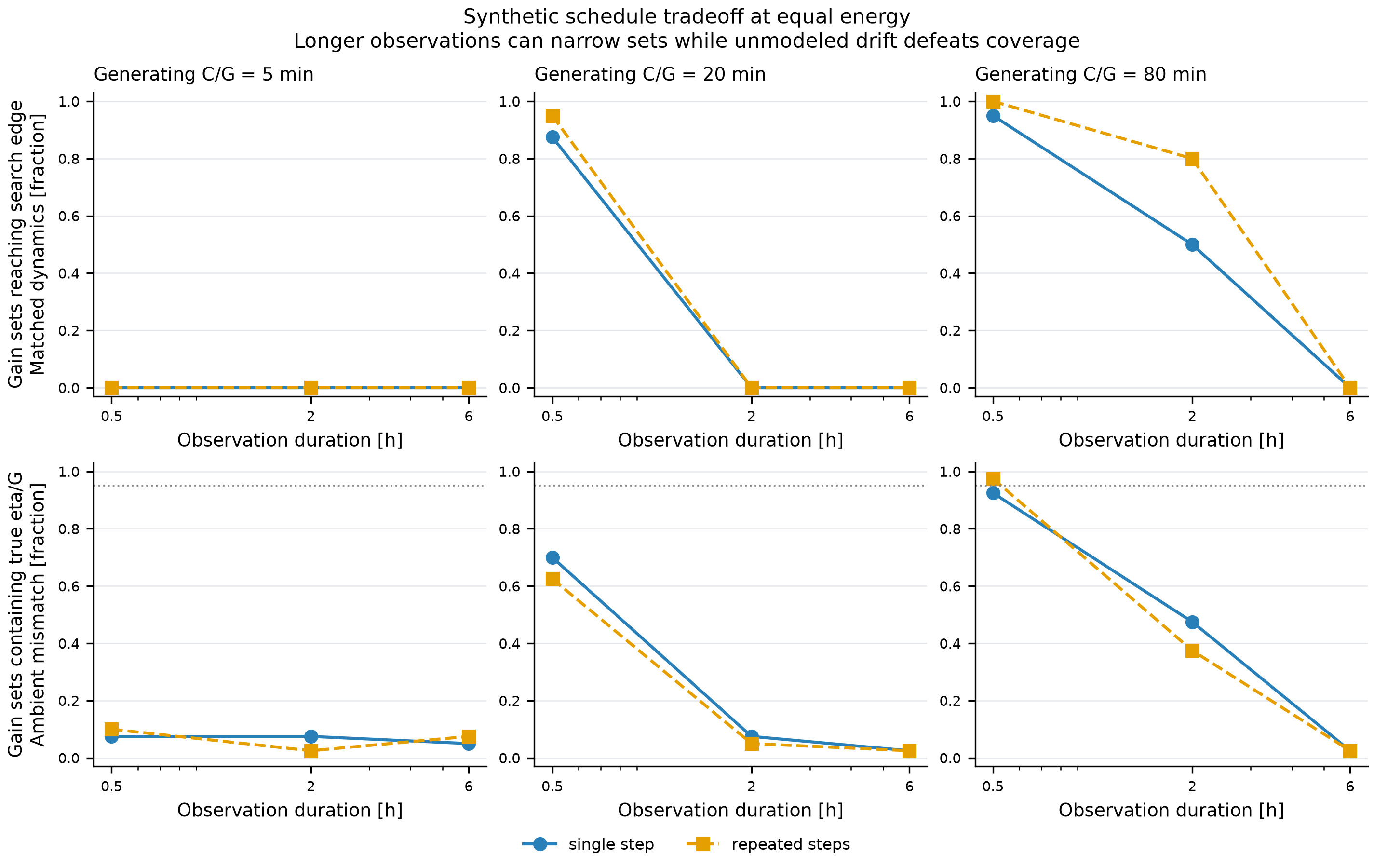
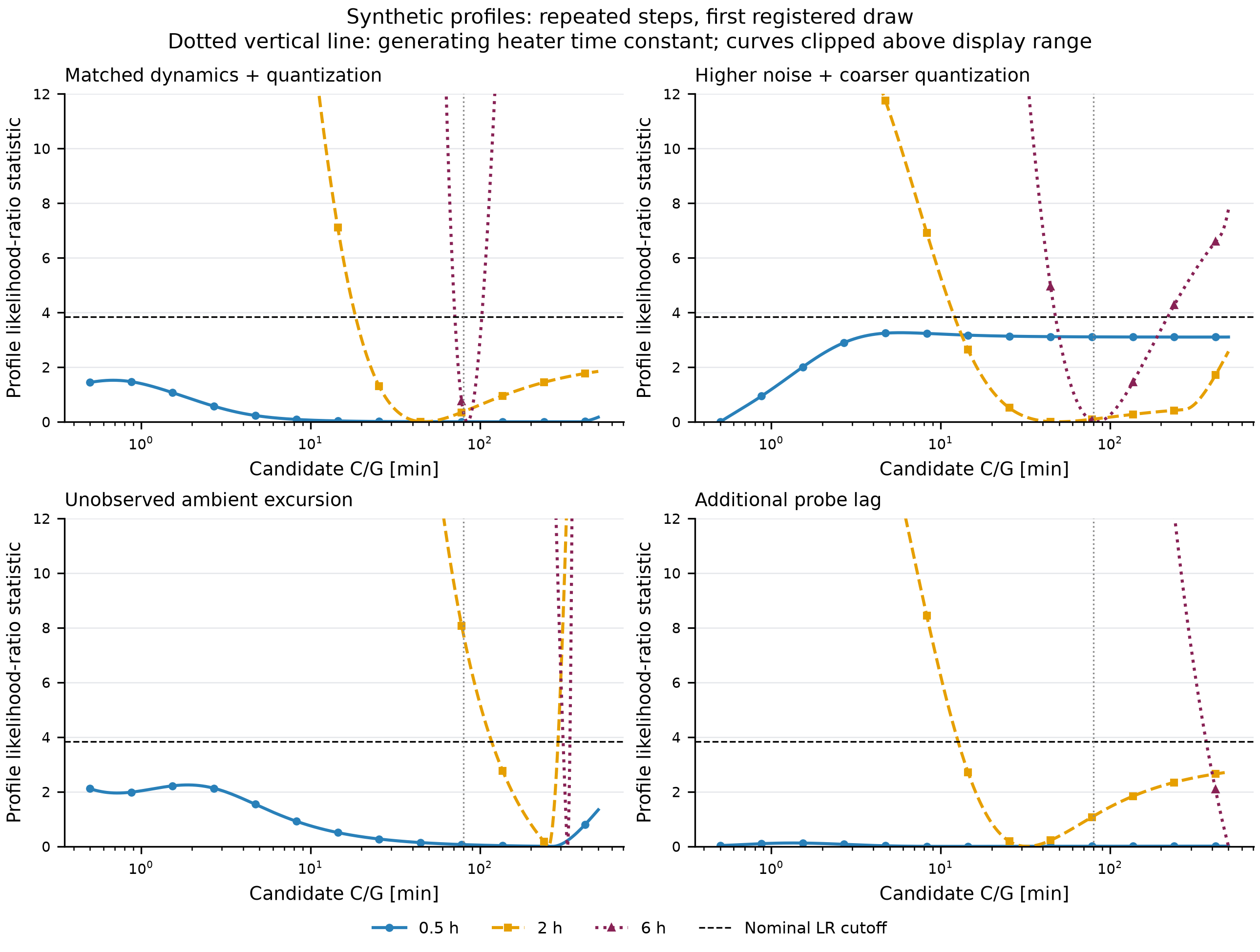
| Power-step identifiability | Determine what the planned heater intervention can estimate before building the rig. | Simulate noise, ambient mismatch and probe lag across registered power schedules. | Power-only records identify C/G and eta/G; jointly scaling C, G and eta leaves the modeled trajectory unchanged. |
design problem
The enclosure has to balance rain paths, sensor airflow, solar heating, mounting loads and access to the electronics. A later partner requirement called for a purchased housing and a new internal layout.
My contribution. I took over enclosure development in December 2025, designed and built four printed revisions, debugged the node power path, modeled enclosure heating, and assembled the Queens College unit. The initial summer-2025 prototype preceded my involvement. Josh Lee wrote the firmware; I reviewed and debugged the posting code with him.
technical details
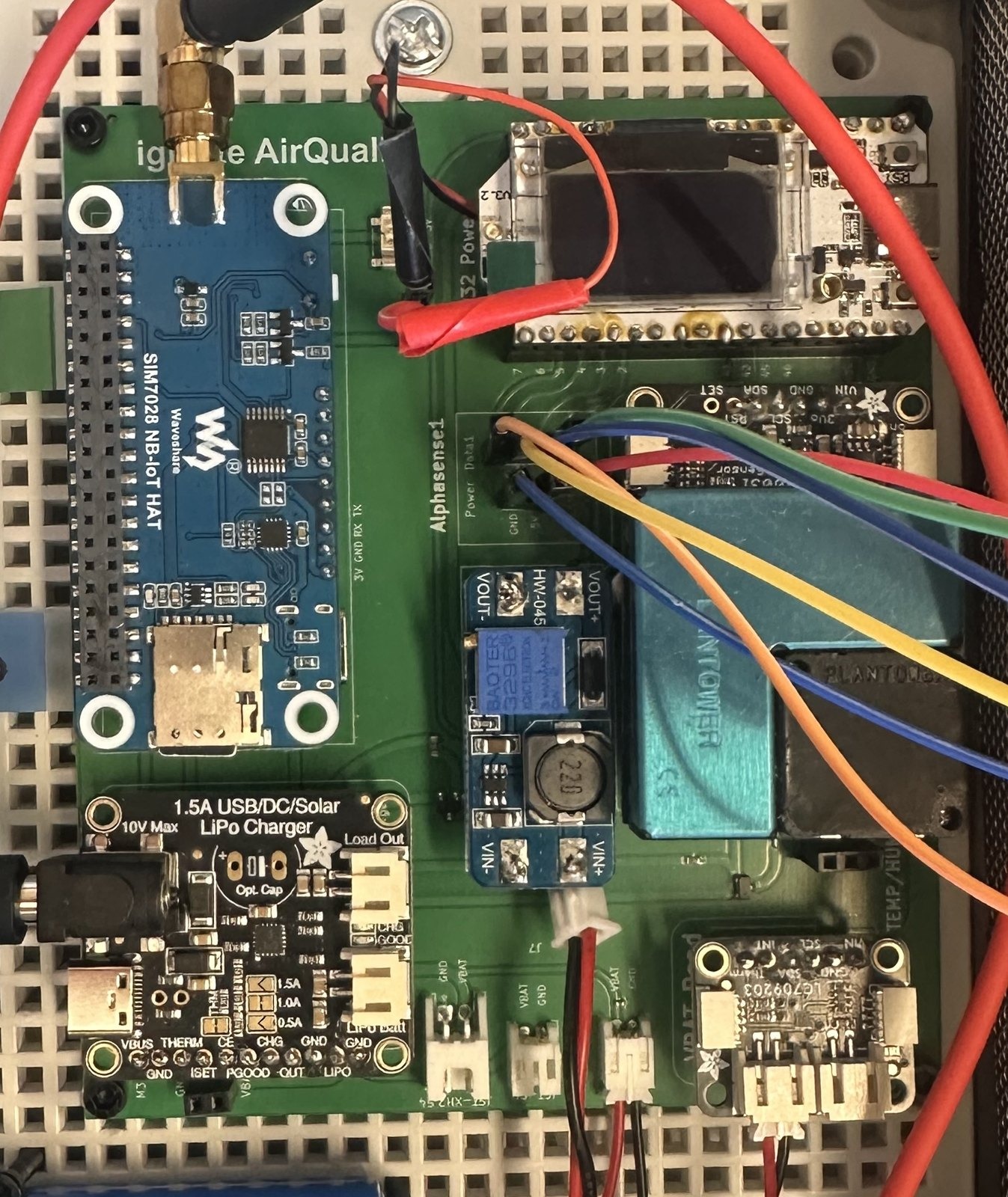
| Queens College packaging | Gas cells on the lid; carrier electronics and a 3.7 V, 5.2 Ah battery on the perforated base plate; hinge-crossing harness, cable glands and a mesh vent. |
|---|---|
| Module integration | Heltec ESP32-S3, SIM7028 NB-IoT modem, Plantower PM sensor, Alphasense gas-sensor boards, BQ24074 charger and fuel gauge. Existing firmware and data path were retained. |
| Power failure mechanism | Concurrent sensor, fan and modem startup loaded the shared supply. Sequential startup and revised power routing addressed the reset loop. The presentation sketch illustrates the mechanism; it is not an oscilloscope capture. |
| Printed-box wind screening | A 140 mph scenario gives approximately 62 N on the side face. A simplified wall-strip calculation gives 0.825 ksi against a 4.5 ksi screening allowable. Large deflection and printed-material assumptions limit this estimate. |
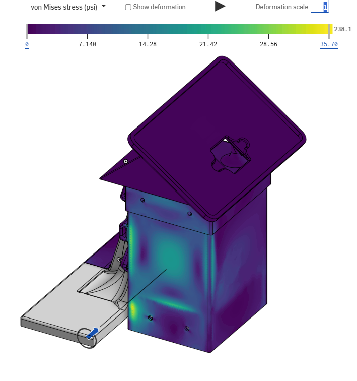
| Separate FEA case | The 55 N linear-static screenshot reports a 238 psi local peak. Support/load-path review and a mesh study remain open; this is not a converged mounting qualification. |
| Thermal comparison | Steady absorbed solar and internal heat are balanced against convection and long-wave exchange. At 1000 W/m² and 0.5 m/s: dark +19.4 °C, white +4.5 °C and passive shield +3.0 °C. Optical and ventilation inputs are assumed; sensitivity can reverse the shield/white ranking. |
| New panel and mount | The deck specifies a 222 × 137 mm panel and fixed 40° bracket for the Queens College build. The offset panel adds a new load path; printed-box wind and thermal results cannot establish this assembly’s capacity. |
| Next checks on this exact unit | Service open–close cycling; spray in installed orientation; low-battery wake cycles with scoped supply measurements; bracket/panel proof loading; and co-location against a reference for calibration. |
methods and scope
Printed-box hand calculations, the separate 55 N FEA and thermal predictions guide design choices; they do not qualify the Queens College assembly. Its five planned checks have no documented passing results. A November 1 recount of the received export found 4,736 records and zero BROWNOUT flags in the April 20–May 11 window identified as V3 outdoors in the presentation. Missing transmissions are not represented, so this is not an uptime or absolute zero-reset claim. Thermal ranking remains sensitive to assumed inputs; co-location and field transfer are unvalidated.
project record
| Evidence | Built enclosures, measured power debugging and model-based screening |
|---|---|
| Status | In Progress |
| Timeline | Dec 2025 – Present |
| Role | Enclosure design, fabrication, integration, power debugging and thermal analysis |
| Tools | SolidWorks, Onshape, FDM Printing, Multimeter, Oscilloscope |